

Electronics Production |
|||||||||||||||||||||||||||||
| Introduction :: | |||||||||||||||||||||||||||||
This week we finally start to learn the most interesting part of knowledge. Because the Electronics part is what I’m weak at.The exercise for this week was to designing and fabricate an own ISP programmer. This includes desgining, milling, soldering and using e.g. an AVR programmer to program the board as an ISP programmer. I chose to follow various tutorials from which I got few clear pictures of the schematic and the board design. Additionally, I also used various student's page as a reference. Let’s begin a new adventure with Roland Mini SRM-20 CNC Router of my lab
|
|||||||||||||||||||||||||||||
This week I had to :- 1)To mill out the PCB for the Fab ISP Programmer |
|||||||||||||||||||||||||||||
| Lets Get Ready for FAB ISP programmer (What is Fab ISP ?) | |||||||||||||||||||||||||||||
The FabISP is an in-system programmer for AVR microcontrollers, designed for production within a FabLab. It allows you to program the microcontrollers on other boards you make. The Electronics Production assignment is to mill the board, stuff it with components and program it. In This ISP we are using Atmel ATTiny-45 micro controller which is 4 K Byte of Memory where as Attiny 85 is 8k byte of memeory. |
|||||||||||||||||||||||||||||
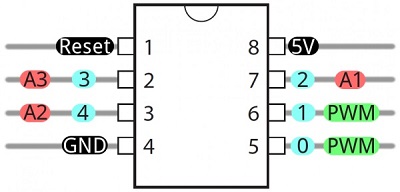
PIN configuration of ATtiny44 |
 |
||||||||||||||||||||||||||||
The machine and the PCB production process |
|||||||||||||||||||||||||||||
In my FabLab, the PCB Milling machine model is SRM-20 . Here are the few features of SRM 20 This machine can be used for PCB milling and drilling other than that this machine can also use for Cuttable Material of Modelling Wax, Chemical Wood, Foam, Acrylic, Poly acetate, ABS. X, Y, and Z Operation Strokes203.2 (X) x 152.4 (Y) x 60.5 (Z) mm Workpiece table size232.2 (X) x 156.6 (Y) mm Distance From Collet Tip to TableMax, 130.75mm (5.15 in) X-, Y-, and Z-Axis Drive System have stepping motor Operating Speed is 6 - 1800mm/min Spindle Motor is DC motor Type 380 Interface is USB Cutting Tool Chuck with collet method Spindle Rotation Speed can adjust i.e Adjustable 3000 - 7000 rpm Dedicated AC adapter: AC 100-240 V ±10%, 50/60 Hz |
|||||||||||||||||||||||||||||
|
|||||||||||||||||||||||||||||
Machine Setting |
|||||||||||||||||||||||||||||
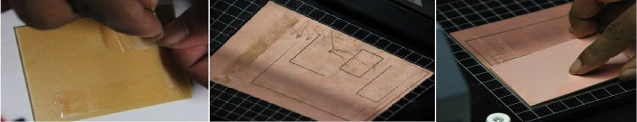
We are using the Monofab SRM 20 milling machine for designing the FabISP. 1) Setting Up the Sacrificial Layer We will be using a copper clad board as our sacrificial layer. We need a sacrificial layer here because in case something goes wrong and the milling bit goes further than expected, we might just end up damaging the base plate. The sacrificial layer as the name suggests sacrifices itself for saving the base plate from any damage.
To do this we apply the dual sided tape onto a copper clad board, about the same or of greater size to that of the plate we are going to mill. This would also help us when we are cutting the final board out. Make sure that when you place the board on the build plate you leave a 1 sqcm border. Make sure that the board is level and apply sufficient force above it to make it adhere to the base plate. |
|||||||||||||||||||||||||||||
 |
|||||||||||||||||||||||||||||
Milling of PCB |
|||||||||||||||||||||||||||||
The purpose of this assignment is to characterize the design rules of our production process.: |
|||||||||||||||||||||||||||||
Prepare to create .rml file using mods |
|||||||||||||||||||||||||||||
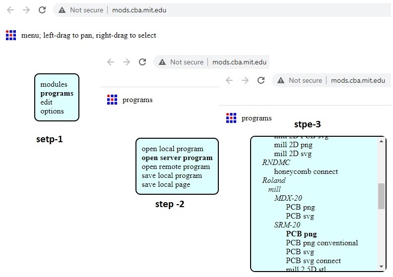
For printing in the SRM20 .rml file, it is required from conversion of .png file to .rml file, which I am going through the mods website: https://mods.cba.mit.edu/ |
|||||||||||||||||||||||||||||
 |
In 4th step it needs to change the x,y,z to zero and in home section z make to 5 mm.As manually i will do the origin setting though the v panel.hence the .rml file creation time it need to care about set origin and home only the z axis have to 5 mm. I did mistake at the time .rml file creation.i was putting it as zero hence it was getting wrong at the time of end the milling job the time of milling.It was jut put a milling from the end to origin i.e z axis is not getting up after milling completion. |
||||||||||||||||||||||||||||
 |
|||||||||||||||||||||||||||||
 |
|||||||||||||||||||||||||||||
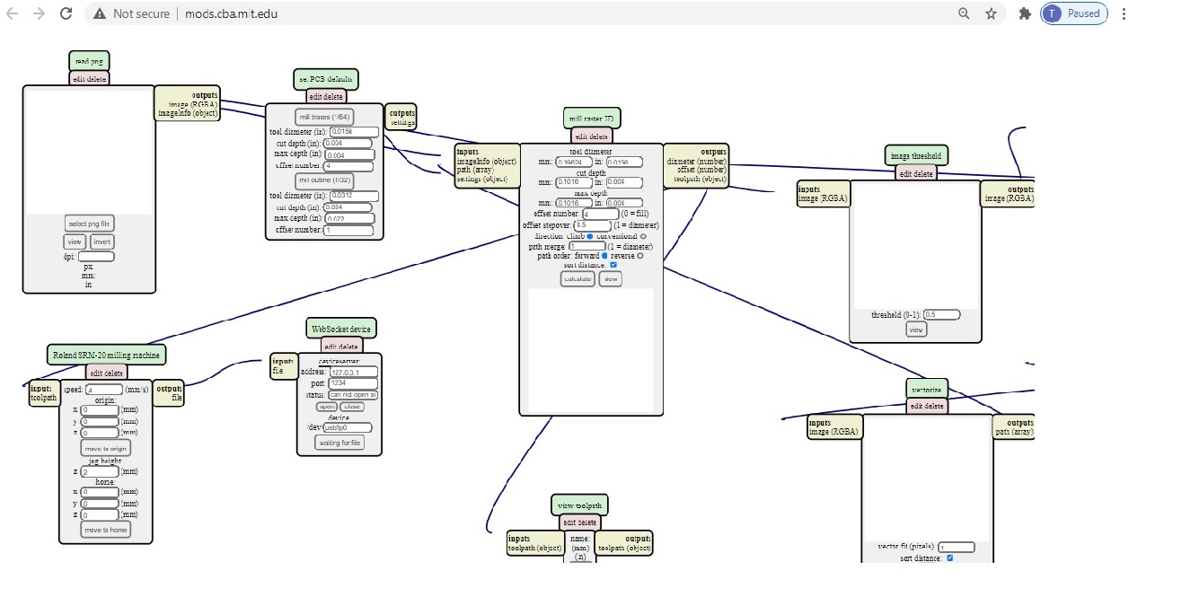
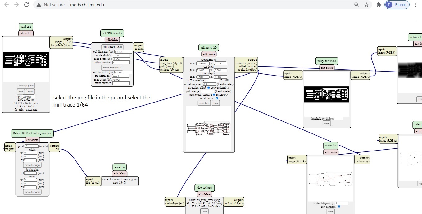
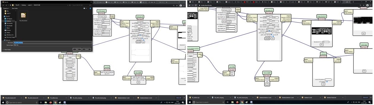
The first thing is to download the traces and interior and then I opened Fabmodule which allow me to decide the reference point also to calculate the tool paths. When I opened the Fabmodule I chose from the input image(.png) then I chose the image then Output format I chose (.rml) because we use SRM-20, in the process we chose PCB traces (1/64) to mill the PCB. |
|||||||||||||||||||||||||||||
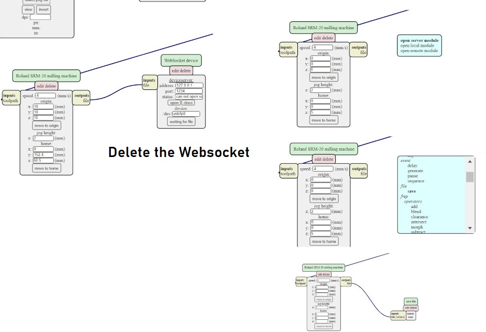
It is required to delete the websocket from the localhost which can provide to save file to local system, hence it very important to first save the.png file of both trace and cut for the circuit to mill the PCB. |
|||||||||||||||||||||||||||||
 |
|||||||||||||||||||||||||||||
For tracing the mods calculation, here it can be put the maximum milling using my SRM 20 maximum i,e. .005 mm. The x,y and z axis can also be defined. |
|||||||||||||||||||||||||||||
|
|||||||||||||||||||||||||||||
|
|||||||||||||||||||||||||||||
 |
|||||||||||||||||||||||||||||
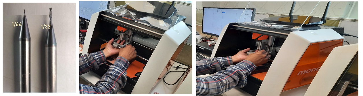
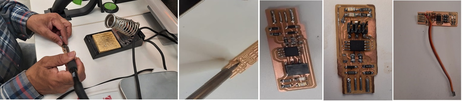
After downloading the .rml file to the local system, now we have to mount the milling bit i.e 1/64 for trace and 1/32 for cut. During the installation of the milling bits we have to be careful by holding it in two finger else anything mishap may happen. |
|||||||||||||||||||||||||||||
 |
|||||||||||||||||||||||||||||
|
|||||||||||||||||||||||||||||
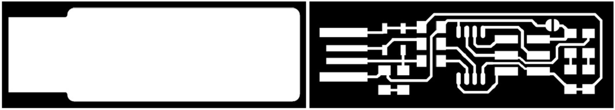
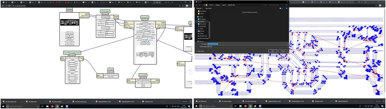
| Now Select the png file with the trace path of the PCB(In my case fts_mini_tracesdeepak.png) | |||||||||||||||||||||||||||||
 |
|||||||||||||||||||||||||||||
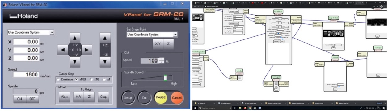
Now we need to set zero for x, y, and z for this Milling which will be a User-Friendly VPanel The SRM-20’s VPanel controller provides a simple interface for adjusting tool position and moving the cursor to set the milling starting point. The VPanel also allows easy control of the feed rate and spindle speed with pause and resume operation, plus tracking of X,Y,Z axis milling with a numeric readout in millimeters or inches. |
|||||||||||||||||||||||||||||
Select traces png file in the mods after V Panel setting and press calculate in mods, which will give us the .rml file to be send to the Monofab SRM 20 to be milled. |
|||||||||||||||||||||||||||||
 |
|||||||||||||||||||||||||||||
 |
|||||||||||||||||||||||||||||
After opening the V panel and set it to the origin and by pressing the X Y for the location from where the job will start milling and after that set the Z by holding the bit. |
|||||||||||||||||||||||||||||
Required Component
|
|||||||||||||||||||||||||||||
|
|||||||||||||||||||||||||||||
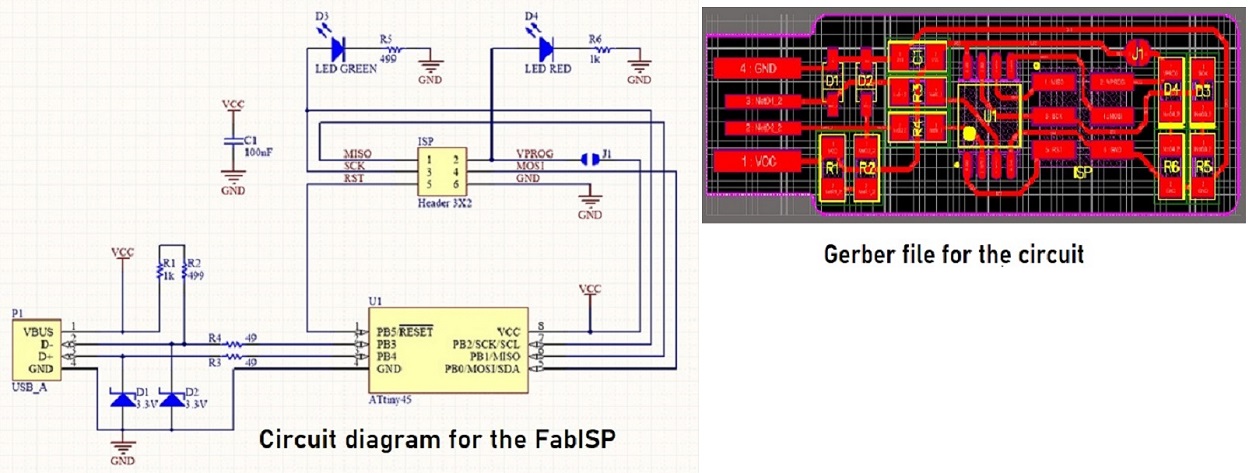
The LEDs and their associated resistors are optional; the red LED lights when the target circuit is powered, and the green LED lights when the programmer is talking to the target.Solder the parts to the PCB, using the schematic and board imagebelow as a reference for component values and placement.Start with the most difficult parts (the ATtiny45) first, so you have the most access.Install the ISP header last, as it is large and can get in your way if you do it earlier. |
|||||||||||||||||||||||||||||
Soldering the Circuit:- |
|||||||||||||||||||||||||||||
Now to solder the required components and put the solder just close to it as the heat in copper layer and then solders melt in same time to remove the solder then automatically solder will deposit into the printed circuit. |
|||||||||||||||||||||||||||||
 |
|||||||||||||||||||||||||||||
Checking the Circuit after soldering:- |
|||||||||||||||||||||||||||||
| First Check the board against the schematic and PCB layout image to make sure that you have installed the correct components in the correct locations and orientations. Inspect your board visually. Components should be flat on the board, not tilted with pins in the air. Soldering connections should be smooth and solder should have flowed both onto the pin and onto the pad. If you still see a lot of exposed copper on the pad or the solder is lumpy and draws up into a point where you removed the iron, you probably don't have a good connection. Reflow by applying heat and flux and also look for unwanted solder bridges between nearby traces and pins. Use a multimeter to check for shorts between VCC and GND | |||||||||||||||||||||||||||||
Programming the Micro controller:- |
|||||||||||||||||||||||||||||
Install Necessary Software for AVR Programming: |
|||||||||||||||||||||||||||||
1) Avrdude (for programming AVR microcontrollers) Open terminal and type sudo apt-get install flex byacc bison gcc libusb-dev avrdude sudo apt-get install gcc-avr sudo apt-get install avr-libc sudo apt-get install libc6-dev Move to desktop cd ~/Desktop |
|||||||||||||||||||||||||||||
Power the FabISP Board |
|||||||||||||||||||||||||||||
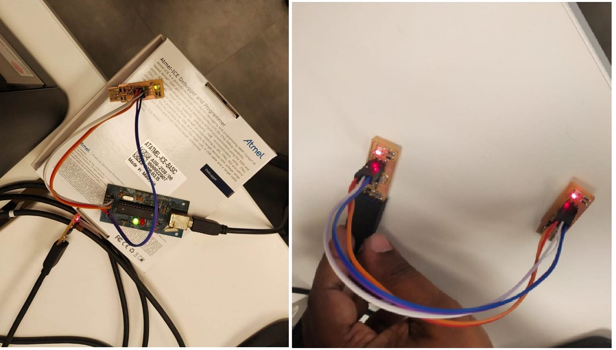
Then connect the FabUSB ISP to your PC to supply the power of 5V to the ISP board and attach another programmer like ATmel ac shown in picture. |
|||||||||||||||||||||||||||||
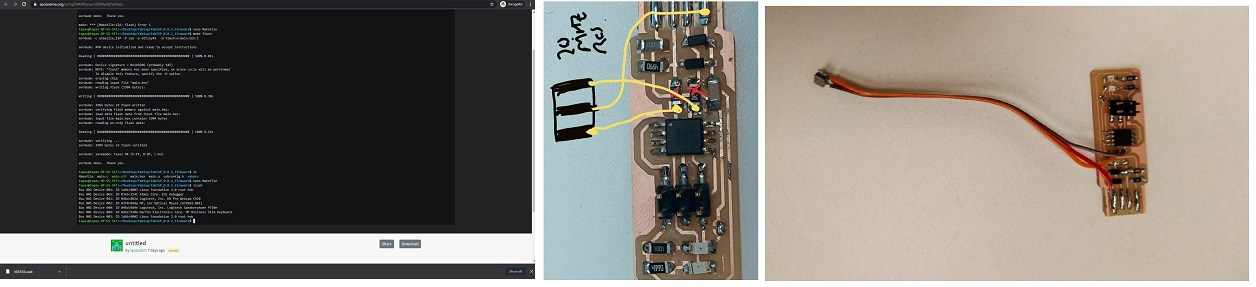
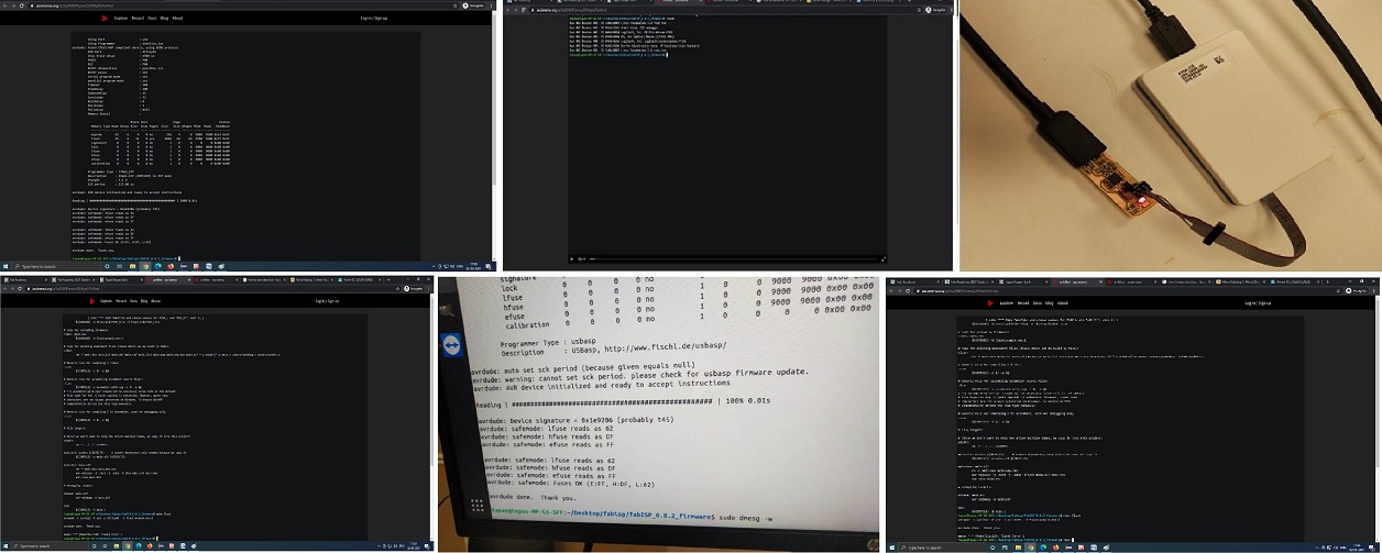
Then I changed the programmer and followed the whole excercise from the begining. I Typed avrdude-c usbasp -p t45 -v It was showing success but on plugging my FAB ISP to USB port of PC it was not detecting. For solving the problem I found that due to the wrong firmware upload of attiny 44 was uploaded in our FAB ISP Attiy 45. Accordingly, I downloaded the correct firmware. But as per our instructor Mr.Sibu, the firmware cant be over written in the same microcontroller. So either i have to change the micro controller or reset the fuse. So I decided to reset the fuse. For this he instructed to connect the 20 Mhz SMD Crystal Oscillator to Pin No 2 and Pin 3 and center connection to Pin 4(Ground) of the Micro-controller. For this i need to remove the two resistors from pin no 02 and 03 and connect thed oscillator. As I am using Windows10, my colleague Tapas used Ubunut OS. Linux is the premier choice by developers of embedded applications for several reasons: from being open-source to scalability, developer support, and tooling, myriad arguments justify why Linux is a great candidate for embedded systems. In Ubuntu CLI terminal the programing is easily done. Oscillators generate the heartbeat of every micro controller and produce clock signals that are essential for synchronizing internal operations. In micro controllers, the clock signals can be generated using either mechanical resonant devices or electrical phase shift circuits. external clock of 20MHZ frequecy, I need to set fuses accordingly before programming. |
|||||||||||||||||||||||||||||
 |
|||||||||||||||||||||||||||||
Accordingly, I downloaded the corrcet firmware from https://github.com/Academany/FabAcademany-Resources/blob/master/files/firmware_45.zip and followed the same excercise and run the command with my FabISP connected to the AVR programmer. >rstdisbl
After that, I disconncted the oscilltor and connected the resistors to the same pins of microcontroller. and followed the above steps to programm the FabISP connected to AVR programmmer and found that my programmer was programmed sucessfully. |
|||||||||||||||||||||||||||||
 |
|||||||||||||||||||||||||||||
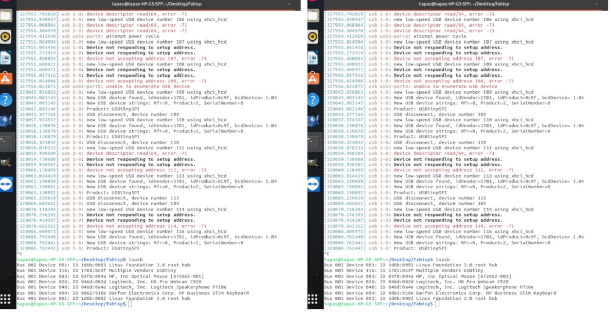
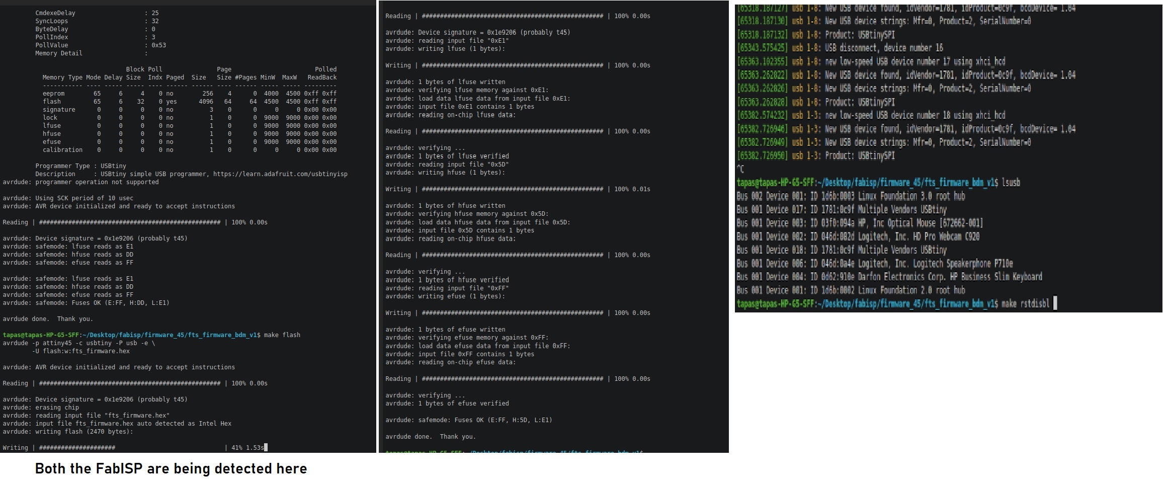
Then I used my ISP to programm the FabISP of my collegeue and type the command on my terminal from the firmware directory >Avrdude -c usbtiny -p t45 -v |
|||||||||||||||||||||||||||||
 |
|||||||||||||||||||||||||||||
and then run the following command >make flash |
|||||||||||||||||||||||||||||
|
|||||||||||||||||||||||||||||
Here is the full video of the whole excercise recorded with Asciinema |
|||||||||||||||||||||||||||||
 |
|||||||||||||||||||||||||||||